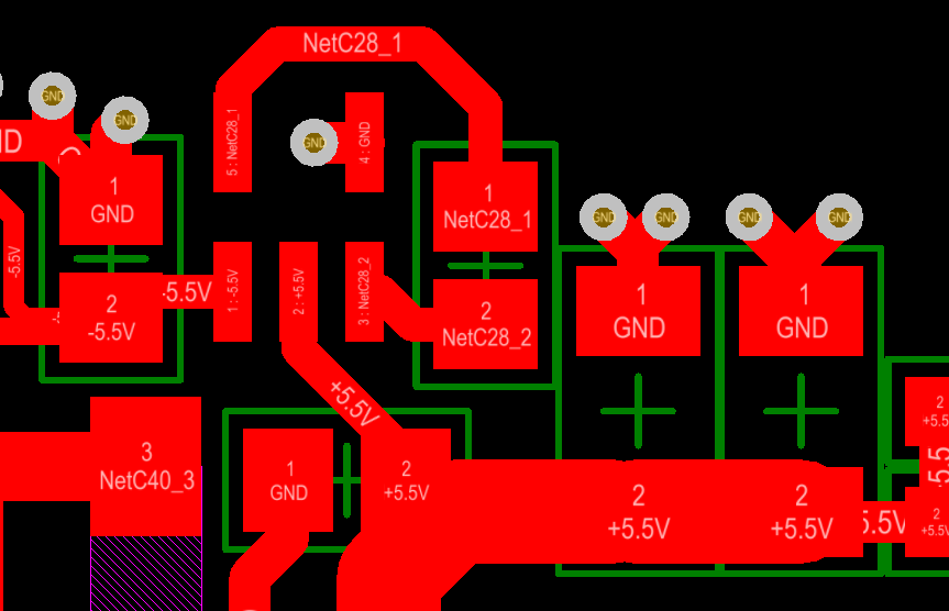
This webpage contains schematic symbol libraries and PCB footprint libraries with 3D details. To view Altium files, you need either the full version of ‘Altium Designer', or ‘Altium Viewer' which can be downloaded for free from Altium's web site. Free symbol and PCB footprint for UJ3-MIABH-1-SMT, compatible with all major PCB tools. Preview and download now!
Question:
Subnautica xbox code. We are just starting to use the OrCAD tools to design PCBs. After I completed the surface mount pad stacks for a board and tried to change the directory so I could change padstacks to through hole connectors, I ran into problems. I received cryptic error messages from the netlist import that I am unable to resolve. How can I organize my library files to correct and avoid this type of issue?
Suggested Solution:
Such error messages occur when there are configuration issues with library paths. By default the PCB Footprint symbols and padstacks are automatically installed with the installation of PCB Editor. These symbols and padstacks are installed in the following directories:
- PCB symbol libraries: C:CadenceSPB_17.4sharepcbpcb_libsymbols
- Schematic symbol libraries: C:CadenceSPB_17.4toolscaptureLibrary
Note: If you are using a different OrCAD version, such as 17.2, the above paths are the same except 17.2 is used rather than 17.4.
The symbols included with the PCB Editor installation are often used as a starting point during development of board design. PCB Editor points to these symbols and padstacks paths by default. As you refine development of your board and update and modify parts, you need to verify your project is reading part information from the correct path. Information presented in the remaining part of this solution article describes how you can verify library paths.
PCB Editor Libraries
The PCB Editor variables that point to the location of the symbols and padstacks are PSMPATH and PADPATH respectively.

You can verify the paths of these variables by selecting the PCB menu, Setup > User Preferences. Your selection opens the User Preferences Editor. Click Paths > Library in the Categories column to expand the library display.
The values associated to the padpath and psmpath variables include lists of directory paths where you have saved your footprints and padstacks. When PCB Editor searches for a part, the search is conducted in the search order of the directory list. If there are multiple instances of a footprint or padstack, the search stops after finding the first match. If the first match is incorrect, board errors result.
To avoid this type of error, the best practice recommendation is to create padstacks and footprint symbols in a separate company directory. This helps separate your company symbols from the installation. It is a matter of personal preference but some users like to keep their padstacks in a directory that is separate from their symbols while others put them together in a single directory. However, there is no performance difference between the two methods.
An example of the path search order of the PSMPATH variable value follows. Download unikey cho mac os.
Orcad Footprint Viewer Image
Capture Libraries
Similar to symbol paths configured for PCB Editor, it is best to keep your company libraries separate from the installation directory. There are several different ways you can configure part library paths of your Capture design or project.
- You can use the Capture, Place > Part menu
- You can add a library to your project manager (File Hierarchy Library folder).
- If using Capture CIP, you can edit the Library section of your capture.ini file.
You can select the Capture, Place > Part menu to open the Place Part window panel. This window includes controls you can select to search for parts and then selectively add a new library to your design or project.
You can also add a library to your design or project from your project manager/File Hierarchy Library folder. Highlight your Library folder and select Add File from the right mouse popup menu. Your selection opens the 'Add File to Project Folder – Library' dialog where you can browse to select the library you want to add.
If you are using Capture CIS, it may be necessary for you to edit the Library section of your capture.ini file.
Configuring a library for a Capture design or project from the Place Part window
Advantages of adding parts from the Place Part window: Harvard business publishing simulation answers.

- The library remains in all designs or projects until removed.
- It's easy to modify the library via the 'Place Part' window GUI.
- The library and path is added to the Place Part window for easy-reference.

Disadvantages of adding parts from the Place Part window:
- A lot of added libraries slows down system operation and Capture start-up
- Library is added without locking the library or creating an OLBlck file
Configuring a library for a Capture design/project from the File Hierarchy Library folder
Advantages of configuring a library part from the File Hierarchy Library folder:

You can verify the paths of these variables by selecting the PCB menu, Setup > User Preferences. Your selection opens the User Preferences Editor. Click Paths > Library in the Categories column to expand the library display.
The values associated to the padpath and psmpath variables include lists of directory paths where you have saved your footprints and padstacks. When PCB Editor searches for a part, the search is conducted in the search order of the directory list. If there are multiple instances of a footprint or padstack, the search stops after finding the first match. If the first match is incorrect, board errors result.
To avoid this type of error, the best practice recommendation is to create padstacks and footprint symbols in a separate company directory. This helps separate your company symbols from the installation. It is a matter of personal preference but some users like to keep their padstacks in a directory that is separate from their symbols while others put them together in a single directory. However, there is no performance difference between the two methods.
An example of the path search order of the PSMPATH variable value follows. Download unikey cho mac os.
Orcad Footprint Viewer Image
Capture Libraries
Similar to symbol paths configured for PCB Editor, it is best to keep your company libraries separate from the installation directory. There are several different ways you can configure part library paths of your Capture design or project.
- You can use the Capture, Place > Part menu
- You can add a library to your project manager (File Hierarchy Library folder).
- If using Capture CIP, you can edit the Library section of your capture.ini file.
You can select the Capture, Place > Part menu to open the Place Part window panel. This window includes controls you can select to search for parts and then selectively add a new library to your design or project.
You can also add a library to your design or project from your project manager/File Hierarchy Library folder. Highlight your Library folder and select Add File from the right mouse popup menu. Your selection opens the 'Add File to Project Folder – Library' dialog where you can browse to select the library you want to add.
If you are using Capture CIS, it may be necessary for you to edit the Library section of your capture.ini file.
Configuring a library for a Capture design or project from the Place Part window
Advantages of adding parts from the Place Part window: Harvard business publishing simulation answers.
- The library remains in all designs or projects until removed.
- It's easy to modify the library via the 'Place Part' window GUI.
- The library and path is added to the Place Part window for easy-reference.
Disadvantages of adding parts from the Place Part window:
- A lot of added libraries slows down system operation and Capture start-up
- Library is added without locking the library or creating an OLBlck file
Configuring a library for a Capture design/project from the File Hierarchy Library folder
Advantages of configuring a library part from the File Hierarchy Library folder:
- Useful if the library contains a part that is only occasionally used
- Provides the ability to create/modify parts as needed
- If you are using Capture CIS, Capture and Capture CIS share the same line section of the capture.ini file. Capture CIS, by default, uses the paths included in the capture.ini file to identify library paths.
Disadvantages of configuring a part library from the File Hierarchy Library folder:
- Creates the lock file, OLBlck, that locks further sharing of the library
- Has no effect on Capture CIS, where lines of the capture.ini file that identify library paths are not automatically updated
Configuring a library for Capture CIS by adding a path to [Part Selector Configured Libraries] of the Capture.ini file
Orcad Footprint Viewer Software
Advantages of adding a library to the [Part Selector Configured Libraries] section of the Capture.ini file:
- Capture CIS always sees the path entry
- Resolves a [Part Selector Configured Libraries]' issue with Capture CIS.
- Section can be given to other users for their Capture.ini file, if common pathing is used.
Disadvantages of editing the Capture.ini file:
- Capture CIS MUST be closed before you apply and save Capture.ini modifications. Otherwise, editing changes are lost.
- Modification of the Capture.ini file must be conducted manually. No GUI for this.
- After you add a part library path to Capture.ini, you must save the file before you start Capture CIS. If pathing is not the same, this section cannot be shared with other users. This section is not used by Capture, only Capture CIS.
Footprint Libraries
While PCB Editor uses the PSMPATH variable to locate the footprint file with the .psm extension, Capture looks for the corresponding footprint file with the .dra extension.
You need to add a section to your capture.ini file to specify where the footprints are stored. Each path that contains footprint symbols needs a separate line. (unlike the PSMPATH variable in the PCB Editor)
Edit your Capture.ini file to add footprint information that may be similar to the lines that follow.
[Footprint Viewer Type]
Type=Allegro
[Allegro Footprints]
Dir0=C:/Cadence/CIP-E/Allegro_Library/symbols/
Dir1=C:SPB_Datacds_sitePCBsymbols
Dir2=C:SPB_Datacds_sitePCBsymbolsUltraLibrarian
Dir3=C:CadenceSPB_17.4sharepcbpcb_libsymbols
